Careful observers of the inner workings of the FCC might’ve noticed that on October 26, 2021, The Public’s Radio was granted a “Construction Permit”, or CP, for WPVD 1290AM.
CP in this case refers to how your Intrepid Engineer applied to modify the broadcast engineering characteristics of WPVD, and the FCC has approved that application. Thus giving us a CP to go ahead and execute the changes. When we’re done, we will file for “Program Test Authority” (PTA) and then, assuming no problems are revealed by the PTA, a “License to Cover” (LtC) meaning the changes are complete and the license has been officially modified.

Normally when a radio station is applying for a CP, they’re looking to improve the broadcast characteristics of the signal somehow. A different power or height. A new directional pattern, or new tower(s) at a different location. Maybe even a different broadcast frequency. The Public’s Radio did this in 2018 after purchasing WNPN 89.3FM and moving it to its current home in Tiverton, RI (the Community of License is Newport, but the tower itself is in Tiverton). In the process roughly doubling the coverage area thanks to a much taller broadcast height. So much so that while the raw Effective Radiated Power (ERP) was slightly lower (from 10,000 to 7,000 watts), the jump in height (from 384 to 900ft Above Mean Sea Level) meant it was still actually an increase in wattage.
But in this case with 1290AM, it seems like quite the opposite: from a Class B three-tower directional array (slightly different at day vs night) with 10,000 watts….to a Class D single-tower non-directional signal at a mere 400 watts day / 16 watts night.
Why on earth would we do such a thing? Well, it’s a lot of little reasons, but they all add up:
- Public radio listeners tend to look for public radio content on the FM Band between 88.1 and 91.9 MHz, because that’s where most public radio stations transmit. It’s hard enough getting them to tune elsewhere on the FM band for our content (like 102.7FM in South County, or 102.9FM in Providence), much less on the AM dial.
- In general AM is a technically inferior broadcast medium to FM, and we already have 89.3FM and 102.9FM covering the same area 1290AM does.
- Furthermore, TPR content hasn’t been regularly airing on 1290AM since 2011. It’d take a lot of time, effort and money to inform & educate our audience to listen to a signal that’s wholly redundant anyways.
- Running a 10,000 watt AM transmitter with different patterns for day & night across four towers is an expensive proposition. The electricity costs alone were over $2000/mo. More in the summer when you had to use more electricity for air conditioning, too. (a 10kW transmitter puts out a lot of waste heat!) And that’s before we get into the need for expensive parts & labor for maintenance costs.
- If we’re going to do something like this, we ought to do it now when we might still get some value by selling the Harris/GatesAir DX10 and Nautel XL12 transmitters. They’re sort of like used cars; the value just ebbs away as time passes.
- We could go all-digital like WSRO 650AM in Ashland, MA just did in early December 2021. Your Intrepid Engineer was sorely tempted. But that’s a lot of time, effort and money invested to improve a signal that, again, is redundant. Plus being all-digital means it sounds great HD Radio digital receivers, but analog receivers hear nothing but white noise.

Speaking more broadly, we still have to keep 1290AM on the air in order to keep our new 102.9FM FM Translator broadcasting in Providence. So simply shutting 1290 off wasn’t an option.
And I also wanted to free up some room in the 1290 transmitter building. We already created an emergency backup air studio out there. And while there’s no firm plans for anything, it’s undeniable that the COVID19 pandemic is completely redefining what “the office” means. I wanted more space to be ready for anything that comes our way.
First things first: we’re taking stuff out…
Actually the very first thing was to determine what broadcast parameters 1290 can have while using just one tower. We contracted the experts that designed 1290’s directional array back in 1998: du Treil, Lundin & Rackley, Inc, and they crunched many, many numbers and came up with an answer: 400 watts by day, 16 watts by night.
Take a moment to realize that means that the old directional pattern was so directional that while it was transmitting 10,000 watts in some directions….in other directions it was only putting out a mere 400 watts during the day, and a paltry 16 watts at night! Broadcast physics is really crazy sometimes!
With that done, we filed our paperwork with the FCC, got approval, and hired the MaxxKonnect Group to do the actual work in November. Their first task was to remove everything that needed removing:
- Disconnect all the high-voltage AC wiring. There’s quite a lot of that.
- Remove the 1-5/8in RF rigid copper conduit/plumbing from the transmitters, phasor, and RF switch.
- Disconnect & reconfigure the 7/8in heliax RF cable running out to the tower field.
- Remove all the audio and telemetry/control wiring to/from the transmitters.
- Remove as much internal components from each TX as we could to lighten the weight (transformers big enough for 10kW transmitters easily weight several hundred pounds each).
- Lay several 1/2in steel pipes to roll the transmitters out of the way.
- Start pulling out salvageable components (coils, switches, insulators, capacitors, spare copper, etc) from the phasor….a process that ended up lasting all week. Also yanking out similar gear from the four ATU’s out in the tower field (that part went a lot faster).
Once we got that done, we set up the new “backup” transmitter: an extensively refurbished LPB AM30 watt carrier-current transmitter. Your Intrepid Engineer was highly amused by this bit of nostalgia, as his first engineering gig (so to speak) was Tech Director at WTBU college radio, an unlicensed-but-legal radio station that used several of these LPB transmitters in a “carrier current” configuration. Seeing what the “refurbs” meant was impressive, though…not much of the original transmitter was left! And what I wouldn’t have given to have those mods back in 1994!
With 1290AM on the air…albeit in limited means – but on the air!…we could keep 102.9FM going while the rest of the work was done. Next up was to clear out the 2.5 existing racks of equipment. Some stuff was being obsoleted and discarded, but a lot was just being moved to new racks. That’s tricky because a lot of it was related to getting our live satellite audio feeds from PRSS to the studio for broadcast. That’s all done using the LiveWire AoIP streams on the satellite receivers, fed into a Telos iPort which turns it into AAC streams across two different ISP’s (OSHEAN fiber and Verizon FiOS) to a twin unit at 1 Union Station, which in turn outputs it as AES3 digital audio from another xNode into our Logitek Audio JetStreamMini studio mixer architecture.
We had to do a lot of prep work, then wait for 11:07am on Saturday. After that newscast at the beginning of Wait, Wait…Don’t Tell Me! there weren’t any more live feeds until the newscast at 3:01pm; everything else was being played locally off the Enco DAD automation computer. So we had a little under four hours to:
- Disconnect the Telos iPort, xNode and xSwitch. Disconnect the Verizon FiOS router. And disconnect the two ATX XDS-PRO4S satellite receivers (and the old SFX4104 receiver that’s only used to provide power to the satdish’s LNB).
- Remove the core gateway (TP Link ER6120 router).
- Move everything over to the new racks in the proper arrangement.
- Re-wire everything up, which – perhaps surprisingly – is what took the longest amount of time.
- Re-establish the iPort connections…which means rebooting both iPorts on both ends which, for some unknown reason, tends to nuke the LiveWire feeds that bring audio from 1 Union Station down to WNPN’s tower in Tiverton, too. Fortunately there’s automatic failover/failback to a redundant STL that uses Worldcast IP Codecs.
- Test the hell out of everything and fix any problems.
I’m pleased to say we got it done with about an hour to spare! After a well-deserved lunch break, we resumed removing the remaining equipment from the old racks…leaving only the OSHEAN fiber router since OSHEAN wanted their own techs to do that move and I was happy to have them do it on Monday; it’s a real trick trying to move fiberoptic cable bundles like that without cutting them in any way. None of us wanted to deal with trying to re-splice it afterwards…it’s a lot of work and requires pretty specialized gear. Let’s just say it was easier to take a big reciprocating saw and hack apart the equipment rack around the fiber router than it would’ve been to re-splice the fiber itself.

We’ve taken stuff out, time to put it back in!
This was a multi-stage process, because it wasn’t just a question of moving equipment from one end of the room to the other. It’s also about adding a bunch of new gear, and also reconfiguring things to work in new ways.
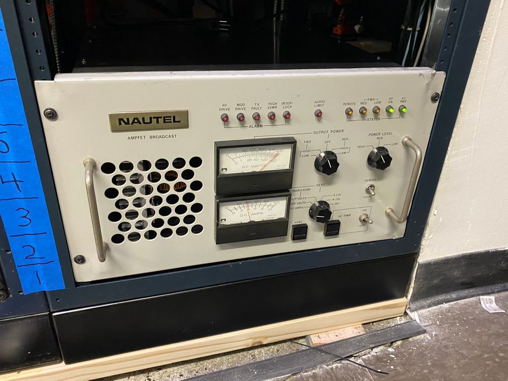
- Main AM Transmitter: a refurbished Nautel P400. One of Nautel‘s earliest designs, which means it’s tough, reliable, and works. MaxxKonnect refurbished it quite a bit, mostly in the power supply area. Solid design or not, power supply technology has come a long way in 40 years. And any power supply that’s 40 years old is probably so worn-out it wouldn’t work anyways. Also has the handy side benefit of dramatically reducing the weight on these notoriously heavy beasts.
- The existing Orban 9200D (PDF) audio processor is still in place. It’s a fabulous-sounding box for AM.
- Aux AM Transmitter: as mentioned above, a cleverly refurb’d LPB AM30 watt transmitter. Not much, but enough to keep us on the air and legal if there’s ever problems with the Nautel P400.

(AceCrew at Amazon.com)
- RF transfer switches: we elected to have very, very basic switching that required a human on-site to do, to minimize cost and maximize reliability. As such, simple little knife switches (mini versions of those giant lever-switches you see Igor pulling when Dr Frankenstein screams “pull the switch!” in the lightning storm) are used to route which transmitter is on the air…main or backup…and to which tower the RF goes to…tower 1/main or tower 3/backup. I cooked up some clever colored lightbulb indicators to show status and help the human in question avoid accidentally switching while a transmitter was still on, or turning on a transmitter that wasn’t connected to any tower.
- Aux FM Transmitter for W275DA: the position of W275DA 102.9FM on the WPRO-FM tower means that if WPRO-FM ever needs tower climbers to work on their antennas, 102.9 has to shut down. This aux facility at 1290 means we can keep 102.9 on the air in some capacity. Our initial testing shows it’s enough to cover downtown and College Hill and I can’t ask it for much more than that. The transmitter is a Harris MicroMax exciter and Harris ZX500 power amp we acquired as part of the purchase of WJHD in November, coupled to a Scala CA2-FM antenna (left over from the original buildout of 89.3 at UMass Dartmouth; it was a receive antenna for 102.7) mounted about 180ft AGL on Tower 1…running through a spiffy new Phasetek Isocoupler. It’s enough to get on the air with about 100 watts ERP.
- We have an Omnia VOLT audio processor installed here for now; it was the VOLT that was used at WELH when we were leasing 88.1FM.
- Monitoring / Radios: we elected to get hardcore on the monitoring of signals here.
- Inovonics 525 AM Modulation Monitor is the primary receiver for 1290AM. Besides providing a measurement reference for adjusting the loudness/modulation of 1290, it also provides audio loss and signal loss alarm contact closures. We’ve had this on 1290 for years, it’s a great little device. It feeds the Nielsen PPM monitor/alarm sensor for 1290 as well.
- Denon DN-300H AM/FM tuner provides additional AM and FM monitoring. We used to have several of these for monitoring purposes at the studios; they’ve been largely replaced by Inovonics “InoMini” receivers.
- Inovonics 531 FM mod monitor is the primary monitor for 102.9FM, and also handy for modulation/loudness adjustment on 102.9’s aux transmitter. This also came from WELH and was available after the end of the lease. The 531 is a great box but it’s limited in that it cannot properly measure an FM signal that has HD Radio carriers present. Many of our signals do have HD Radio so while putting an 531 here is kinda overkill, we don’t have a better use for it at the moment.
- Dayton AF200 FM receiver. Originally used to receive 89.3 to be rebroadcast on 91.5FM, this receiver has the advantage of having a composite output. We leave it set to 89.3 and, in a pinch, I can connect it to the Harris MicroMax exciter directly to rebroadcast WNPN.
- Telos Xstream ISDN codecs: isn’t ISDN dead? Well, yes, actually…it mostly is in Providence and lot of the country. But these old Xstreams can, just barely, also function as webcast encoders. They have the right codec settings to mimic what our primary webcast encoder (a Telos Z/IPstream R/1 at 1 Union Station) can do, so Streamguys has it set up so that if the main webcast fails for some reason, it will smoothly and automatically transition to the backup encoder.
- Harris Intraplex STL Plus w/IP upgrade: These units used to be our primary transport for getting audio from the satellite receivers to the studio at 1 Union Station. There were few devices better for that purpose, but they were designed to use T-1 lines for the connection and those are almost nonexistent these days…and where you can get them, they tend to be very expensive. Harris offered an upgrade package to use IP connections, but as we found: it’s pretty clunky. Still, it does work and it offers a nice, low-delay, redundant audio path between the satdish and 1 Union Station.
- Backup Enco DAD Automation: this proved to be a curveball. After we powered off the computer and moved it to the new rack? Pressed “power on” and….nothing. Power supply died on us. Then we quickly discovered nobody makes that style of power supply anymore. A frantic run up to Microcenter in Boston acquired a workable power supply…but the air vent is on the top, not the side. So we had to leave the lid off the case. Also the PS itself doesn’t quite fit properly so none of the screw holes line up. Grrr. But hey, it’s back up and running and that’s what matters. Besides being our backup Enco DAD, it’s also how both the main and backup DAD get non-live/file-based audio off of the satellite receivers and over to 1 Union Station. Needless to say, new cases are on order. Durn supply chain disruptions.
- Control By Web Remote Control: last but not least, a whole new remote control system to replace the evil-evil-evil Sine Systems RFC1B. Okay, okay, I’m hating on the Sine even though I know some folks really love them. Granted, the Sine was the first…I believe…remote control that would actually run macros based on months. Meaning you could configure it to switch between day/night power at sunrise and sunset at a specific time for every day in the month of, for example, January. That’s important because that’s how the FCC does it. But those Sines had no interface beyond a telephone interface, and it was reeeeeeally clunky. You had to spend a lot of time writing down exactly what keys you were gonna press at specific times in a specific order, before you began anything. Control By Web isn’t really a radio broadcasting company but they’re starting to get used by more and more broadcast engineers because the products work pretty well and they’re comparatively inexpensive. We got an X400 control unit, plus X19 and X22 interfaces. All wired up onto a nice swinging-hinged panel using a bunch of Wago terminal blocks to make wiring today (and changes in the future) a snap!
Time to move to the Great Outdoors…

Of course, it wasn’t just work inside the building that had to be done. There was plenty of things to do out in the tower field as well!
A lot of the trickiness of dealing with AM towers, particularly series-fed towers like 1290, is that the tower itself cannot have any connection to a ground; if it did, all the RF energy you want going out into the air will, instead, flow through that connection into the earth and go, well, nowhere. If you look closely at the base of Tower 1, there’s a thick porcelain insulator (about the size of a can of spray paint) that the whole tower sits on. And the guy wires themselves have several porcelain insulators to break any path to ground. So you have to use some specialized gear that technically is all well-established physics (but it feels like black magic to me) to make wired connections to the tower. In our case, a lightning choke and an isocoupler.
- Ransack the Antenna Tuning Unit (ATU) cabinets for Towers 2 and 4, as they weren’t gonna be used anymore, and we wanted to ensure they would be completely “floating” relative to earth ground.
- Remove any unessential gear from the ATU on Tower 3 (backup tower) to make it simpler.
- Re-wire the 7/8in heliax from Tower 4 to be the new FM RF cable for 102.9, and add another 200ft of 1/2in heliax to go up the tower to the FM antenna.
- Remove the static dissipater on Tower 1’s ATU, and replace with a lightning choke that doubles as a path to bring 110VAC power out to the base of the tower. That power is for the UBNT AirFiber AF5 and LiteBeam LBE-5AC-GEN2 wireless ethernet radios. The former will, eventually, connect to a twin on the WNPN tower in Tiverton (extending OSHEAN fiber connectivity to that site), the latter is to connect from this tower to the building 600ft away. It’s cheaper & easier than trying to run new cable through the conduits.
- Drive some 7ft garden stakes into the earth by the tower and mount the isocoupler to that, then run the 1/2in heliax into either end and properly seal up the connectors to protect them from rain/wind/snow.
- Re-tune all the copper coils in ATU 1 and ATU 3 to make the towers as efficient as possible, using a Vector Network Analyzer (not unlike this one) which are amazingly cheap, easy to use, and effective for something like this.
We ended up having to bring a local expert out with his own VNA to do another sweep/re-tune, because your Intrepid Engineer forgot two things, one small and one big. The small one was that the isocoupler and the NEMA weatherproof box the AC power goes into on the tower? That didn’t arrive until after the MaxxKonnect guys had to leave. I installed them myself, no big deal. But I forgot that even small changes of any kind will still shift the impedance match between the tower and the ATU. So to have minimal VSWR (mismatch), we had to re-tune it.
The big thing was that I thought you could mount an isocoupler to the tower itself and that when you do so, you ground it to the tower itself. The former is technically possible (although a call to Phasetek revealed that “you really shouldn’t do that”) but the latter is causing the exact problem I wanted to avoid: it’s grounding an electrically “hot” tower. Fortunately with the low power levels (the Nautel P400 folded back immediately unless we dialed it down to 30 watts) there wasn’t any physical damage being done. But the signal reach went immediately to hell. As I said, I called Phasetek and after exchanging some pics via my iPhone, they made some suggestions about how/where to mount the isocoupler (on separate garden stakes near the base of the tower) and to connect the “RF GND” lug on the isocoupler to the “station ground”, meaning the ground radial system that begins on the bottom side of that fat porcelain insulator the tower is sitting on. It’s primarily there to deal with a lightning strike which, fortunately, is a fairly rare occurrence on these towers. With that all taken care of, things worked swimmingly!
Not quite done yet!
So there was one big thing left to do on this project: measure the signal to confirm it’s actually omni directional. The FCC gives some specific guidance on that front so your intrepid engineer loaded up the Potomac Instruments FIM-41 “Field Intensity Meter” into the car, and headed off to six points on the map…determined using Google Earth. Specifically, I headed out to a 2 mile radius and got as close as I could to the azimuths of 0, 60, 120, 180, 240 and 300 degrees so long as I was exactly 2 miles out, then repeated the process at 1 kilometer.
Conveniently, the FIM-41 has instructions on how to take a reading printed right inside the cover. It took four hours to drive to each site, find the exact spot I wanted to be, take a bunch of readings to ensure I had a valid one, and then drive to the next site. But in the end, I got readings that confirm the signal is indeed omni-directional.
Now all we have to do is file our paperwork with the FCC and it becomes official: 1290 might be at a lower power, but it’s a lot cheaper to operate and that frees up more resources for journalism!


Leave a comment